
Complete Guide to Alfa Laval PureBallast QT201-50 UV Sensors – Working, Maintenance & 4 Model Differences
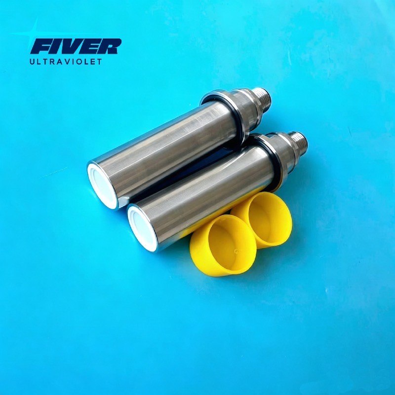
The QT201-50 UV sensor (OEM SUV 20.2 Y2 C 40° by UV-TECHNIK) is the core control component of all Alfa Laval PureBallast 3 BWMS. Mounted on UV reactor housings, it continuously measures UV irradiance to regulate lamp power, stabilize treatment flow and maintain IMO/USCG compliance. A faulty or mismatched UV sensor triggers system alarms, halts ballast operations and risks port state control (PSC) detention.
Four official part numbers cover two major system categories: standard Non-Ex sensors for regular merchant ships, and fully glue-filled EX explosion-proof sensors for tankers, LNG/LPG carriers and offshore vessels. This guide breaks down sensor functions, operation, maintenance rules and critical differences between the four variants.
1. Core Functions of QT201-50 UV Sensor
The UV sensor acts as the closed-loop feedback brain for the PureBallast control system, with five irreplaceable core duties:
Dynamic UV lamp power adjustmentThe PLC relies on real-time W/m² readings to dim or boost 3kW/6kW medium-pressure UV lamps between 50–100% output. Clear high UV-transmittance seawater reduces lamp power to save fuel; turbid coastal water ramps power up to guarantee disinfection dose.
Treatment flow limitation controlPer official PureBallast 3.2 algorithms, UV intensity thresholds set maximum allowable flow: 210 W/m² for marine water, 410 W/m² for fresh water. If readings drop below limits, the system automatically cuts flow to avoid non-compliant discharge.
Alarm & fault detection triggerFouled, damaged or disconnected sensors activate W151/W152 UV signal loss warnings, even critical A-class shutdown alarms that block ballast/deballast processes until repair.
Compliance data loggingAll UV intensity trends and runtime data are stored in the PLC’s 24-month event log. Surveyors and PSC inspectors require this record to verify consistent ballast water disinfection.
Reactor safety auxiliary monitoringIt works alongside reactor level switches and temperature transmitters to prevent dry lamp operation and reactor overheating, extending quartz sleeve and lamp service life.
2. How the QT201-50 UV Sensor Operates
Internal Structure
40° anti-fouling optical lens (316L stainless steel, direct contact with ballast water)
UVC-specific silicon photodiode to capture germicidal 254nm UV output
Signal amplification PCB converting light signal to standard analog data for the PLC
Two distinct housing constructions: open standard assembly (Non-Ex) or flame-retardant glue potting (EX series)
Step-by-Step Working Process
During ballast/deballast, UV lamps ignite inside synthetic quartz sleeves, releasing UVC radiation into the water stream.
Partial UV light penetrates the reactor wall to the sensor’s optical window.
The photodiode generates micro-current proportional to UV irradiance (W/m²).
Internal circuitry amplifies the signal and transmits real-time intensity values to the CC 3.2 Ex control cabinet.
The HMI PLC cross-references readings with built-in compliance curves to adjust lamp power and flow instantly.
15-minute and 1-hour UV trend charts auto-record all data for troubleshooting and inspection archives.
3. Onboard Maintenance & Calibration Rules (PureBallast 3.2 Manual Standard)
3.1 Routine Maintenance Schedule
| Task | Frequency | Operating Standard |
|---|---|---|
Optical lens inspection | Every CIP cycle (max 30 hours post treatment) | Check scaling, salt and biological fouling that distorts UV readings |
Manual lens cleaning | Monthly, or after muddy coastal ballasting | Drain and isolate reactor, wipe lens with Alpacon Descalant Offshore and soft lint-free cloth; avoid lens scratches |
Full sensor inspection | Annual class survey | Check cable glands, wiring corrosion and housing sealing; EX models require extra glue potting integrity inspection |
Spare part stock | Permanent onboard storage | Keep one identical part number spare sensor to eliminate port downtime |
3.2. Calibration Critical Note
QT201-50 sensors are factory pre-calibrated and cannot be adjusted or re-calibrated on board or via field service. All calibration parameters are sealed inside the internal circuit. If cleaning cannot recover stable, accurate readings, full sensor replacement with the matching OEM part number is the only valid fix. After installing a new sensor:
Complete a full ballast test cycle
Navigate to HMI Page 3.5 UV optimization trend chart
Confirm smooth 0–1000 / 0–3000 W/m² signal output
Archive the new sensor’s factory calibration certificate for class surveys
4 Common Sensor Faults & Root Causes
Persistently low UV readings: Heavy calcium scaling or biofouling on lens, cracked quartz sleeves blocking UV light
Fluctuating unstable signals: Loose M12 signal connectors, corroded wiring glands
Complete signal loss: Water intrusion inside housing (highest risk for damaged glue-filled EX potting)
Constant non-compliant warnings: Mismatched sensor range (1000 W/m² fitted to high-flow 6kW reactors)
5. Full Comparison of 4 PureBallast UV Sensor Models
Two core product lines separate by explosion protection design:
Non-Ex range: 9001357 01 (1000 W/m²), 9001357 03 (3000 W/m²) – open PCB, no glue filling, safe machinery room only
EX range: 9008373 01 (1000 W/m²), 9008373 02 (3000 W/m²) – fully glue/potted electronics, ATEX/IECEx Zone 1 IIC T4 certified for hazardous zones
Side-by-Side Comparison Table
| Parameter | 9001357 01 Non-Ex 1000 W/m² | 9001357 03 Non-Ex 3000 W/m² | 9008373 01 EX Glue-Filled 1000 W/m² | 9008373 02 EX Glue-Filled 3000 W/m² |
| Measuring Range | 0–1000 W/m² | 0–3000 W/m² | 0–1000 W/m² | 0–3000 W/m² |
| Internal Build | Open PCB, no potting glue | Open PCB, no potting glue | Fully encapsulated glue potting | Fully encapsulated glue potting |
| Hazard Certification | None (Safe Zone only) | None (Safe Zone only) | ATEX / IECEx Zone1 IIC T4 | ATEX / IECEx Zone1 IIC T4 |
| Compatible BWMS | PureBallast 3 Std / Compact Flex Non-Ex | Large-flow Non-Ex reactors (1000/1500) | All PureBallast 3.2 EX small/medium units | PureBallast 3.2 EX high-flow 1000/1500/3000 |
| Matching UV Lamp | 3kW reactors | 6kW high-power reactors | 3kW EX UV reactors | 6kW EX UV reactors |
| Suitable Vessels | Bulk, container, RoRo, general cargo | Large ore/container carriers | Crude/product tankers, small chemical ships | Large chemical tankers, LNG/LPG, offshore rigs |
| Max Cable Length to LDC | 30m limit | 30m limit | Up to 150m long-distance wiring | Up to 150m long-distance wiring |
| Core Restriction | Cannot use on Zone1 tanker systems | Cannot use on Zone1 tanker systems | Forbidden on Non-Ex units (PLC parameter mismatch) | Cannot substitute with 1000 W/m² EX sensor |
Individual Model Introduction
1. 9001357 01 Non-Ex 1000 W/m²
Low-range standard sensor for small and medium 3kW PureBallast Non-Ex reactors, widely installed on medium-size bulk and container vessels operating in non-hazardous machinery spaces. Not suitable for high-turbidity water where UV intensity exceeds 1000 W/m². Never swap with the 3000 W/m² variant, as PLC calibration curves differ entirely.
2. 9001357 03 Non-Ex 3000 W/m²
High-range Non-Ex sensor built for large 6kW UV reactors on ultra-large merchant vessels with high ballast flow capacity. Designed to handle peak UV output in heavily turbid coastal waters. Only deploy on standard non-tanker BWMS without flammable cargo risk.
3. 9008373 01 EX Glue-Filled 1000 W/m²
Explosion-proof sensor with full flame-retardant glue potting to eliminate internal electrical sparks, complying with Zone 1 hazardous area standards. Matches 3kW UV reactors on small and medium PureBallast EX tankers, including product and light chemical carriers. The sealed glue layer is mandatory for pump room and open deck EX skid installations.
4. 9008373 02 EX Glue-Filled 3000 W/m²
Top-tier explosion-proof UV sensor for large 6kW EX reactors on chemical tankers, LPG/LNG carriers and offshore facilities. Its 3000 W/m² measurement range supports maximum UV power output under low UVT seawater conditions. Critical rule: Installing any non-Ex 900135 sensor on PureBallast EX equipment invalidates ATEX certification and will trigger class survey rejection.
6. Critical Selection & Replacement Guidelines
Strictly separate Non-Ex and EX sensor families 9001357 open-board sensors lack explosion safety construction. Fitting them to tanker Zone1 equipment creates ignition hazards; surveyors will fail the BWMS and order vessel detention. All EX systems must use glue-filled 9008373 variants only.
Match exact W/m² measuring range 1000 W/m² and 3000 W/m² sensors carry unique factory calibration data hard-coded into the sensor chip. Cross-installation leads to permanent low-dose non-compliance alarms that cannot be cleared via HMI parameter adjustment.
Protect EX glue-filled potting structure The sealed glue encapsulation is not a minor design upgrade but a legal certification requirement. Any crack or breakage of the potting compound voids IECEx/ATEX approval, requiring immediate sensor replacement.
Standardize spare parts per vessel PMS Ship managers and yards must list the exact OEM part number in planned maintenance schedules. Mismatched spare sensors cause costly dockside delays during global port calls.
Conclusion
The QT201-50 UV sensor is the performance foundation of every Alfa Laval PureBallast ballast water system. The four available models are split by two decisive technical factors: glue-filled explosion-proof encapsulation (EX vs Non-Ex) and UV intensity measuring range (1000 / 3000 W/m²). General cargo, bulk and container vessels operating without flammable cargo risks can adopt cost-effective 9001357 Non-Ex sensors. All tankers, LNG/LPG and offshore fleets with Zone1 hazardous atmospheres must exclusively specify the fully potted 9008373 EX series. Consistent lens cleaning and stocking matching OEM spare sensors eliminate PSC delays and sustain long-term IMO and USCG ballast water compliance. Need a replacement UV Sensor for your Alfa Laval Ballast Water Treatment System? Fiveruvc is your first choice for high-quality, pre-calibrated, cost-effective replacement sensors.
Post time:2026-07-17
