
Table of Contents
1. Why Temperature Matters in UV BWTS
A UV ballast water treatment system like the Alfa Laval PureBallast generates enormous heat. Each medium-pressure UV lamp draws 6 kW and converts only a fraction into germicidal UV-C light — the rest becomes heat. A typical reactor houses 6 to 16 of these lamps simultaneously¹.
Under normal conditions, flowing ballast water carries this heat away. But when flow drops — a stuck valve, a clogged strainer, a pump losing prime — reactor temperature climbs fast. At elevated temperatures, UV lamp output shifts spectrally, quartz sleeves degrade from thermal stress, O-ring seals fail, and the UV dose may drop below the IMO D-2 threshold. Non-compliant discharge means detention, fines, or both.
This is why the PureBallast system installs not one, but two independent temperature devices inside the reactor, operating as a layered defense system.
2. The Threefold Heat Protection System
Here's something most BWTS operators don't fully understand: the PureBallast doesn't have a single temperature shutdown point. It has three, triggered by two different devices through two different control paths².
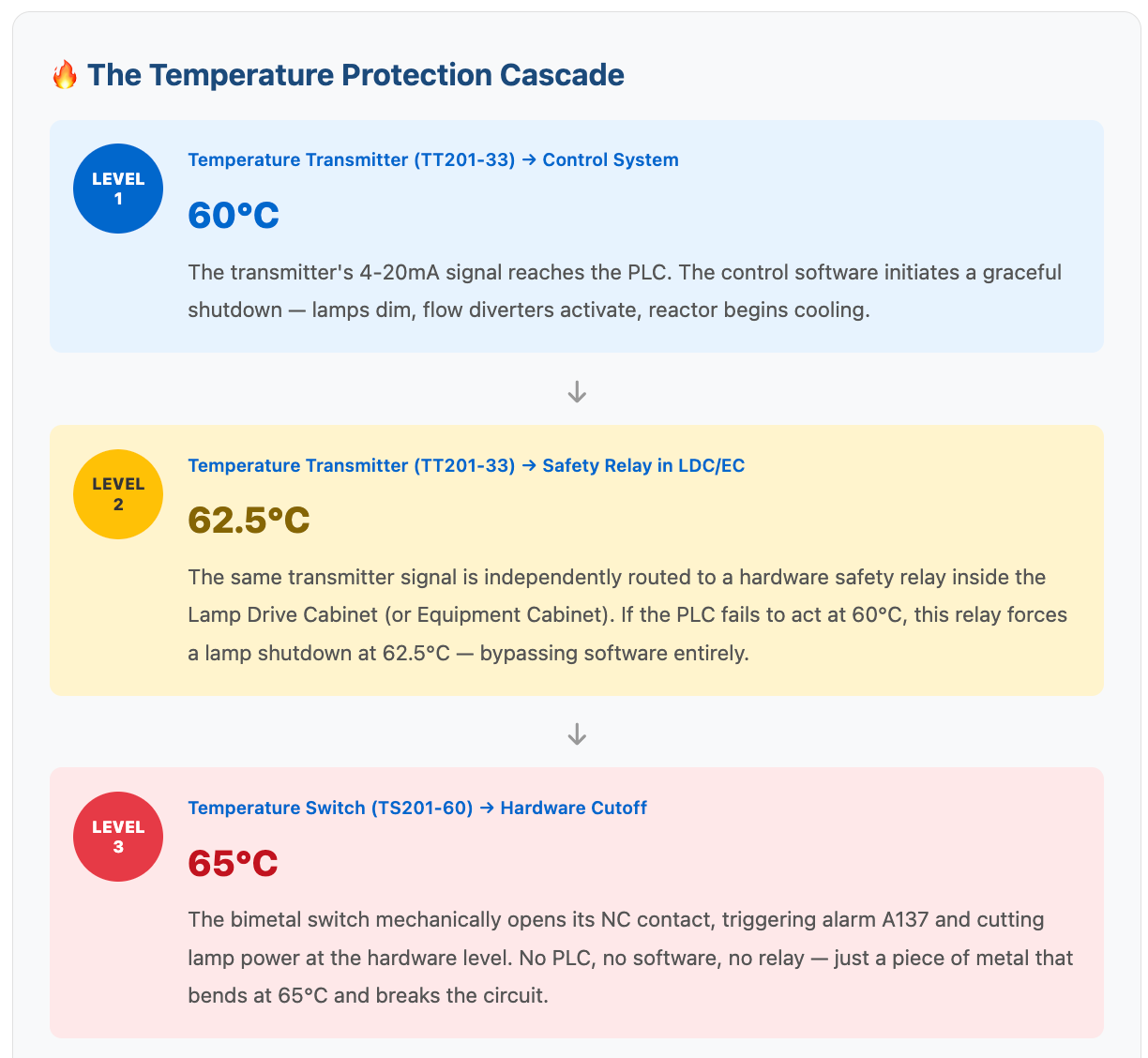
Why three levels? This is defense-in-depth architecture borrowed from safety-critical systems in nuclear and aviation engineering. Level 1 is software (can fail if PLC crashes). Level 2 is hardware relay (can fail if relay sticks). Level 3 is pure physics — a bimetal strip requiring no power, no software, and no relay. It will trip even if every other system on the vessel has failed.
If you've ever wondered why the PureBallast has both a transmitter and a switch when they seem redundant — this is why. They're not redundant; they're complementary layers with different failure modes.
3. The Two Devices: Transmitter vs Switch
Temperature Transmitter (TT201-33, P/N 9006325-02)
An electronic sensor based on a PT100 RTD element — platinum wire with a resistance of exactly 100 ohms at 0°C. As temperature rises, resistance increases predictably, and the transmitter converts this into a 4-20 mA analog signal for the PLC.
The transmitter serves three functions: (a) continuous temperature monitoring displayed on the HMI and logged for compliance records; (b) UV dose compensation — the PLC uses real-time temperature as one of four inputs (alongside UV intensity, water transmittance, and flow rate) to calculate actual germicidal dose; (c) two-stage shutdown control at 60°C and 62.5°C as described above.
| Part Number | 9006325-02 |
| Sensor Type | PT100 RTD |
| Output Signal | 4-20 mA analog (loop-powered) |
| Accuracy | ±0.5°C (Class A PT100) |
| Protection Class | IP68 (submersible) |
| Calibration | Annual; acceptance ratio 0.95-1.05 |
| Emergency Kit | Mandatory spare, item #2 of 8 |

Temperature Switch (TS201-60, P/N 9006324-02)
A bimetal snap-action switch — no electronics, no power supply, no software. It contains a bimetallic strip (two metals with different expansion rates bonded together). At 65°C, the differential expansion causes the strip to snap, instantly opening a normally closed (NC) electrical contact. This breaks the safety circuit, triggering Alarm A137 and cutting lamp power at the hardware level. The system cannot restart until temperature drops to ~45-48°C (automatic reset) and the operator performs a manual reset.
Why does a mechanical switch still exist in 2026? Fail-safe independence. If the PLC crashes, the safety relay sticks, or the transmitter's electronics die — the bimetal switch needs no power at all. It will trip on physics alone. This is the same principle that keeps bimetal thermal switches in aircraft engine controls and nuclear reactor scram systems. When everything else fails, physics doesn't.
| Part Number | 9006324-02 |
| Switch Type | Bimetal snap-action (mechanical) |
| Contact | Normally Closed (NC) — fail-safe |
| Trip Temperature | 65°C (149°F) ±5°C |
| Reset Temperature | ~45-48°C (automatic) |
| Alarm | A137 |
| Technology Base | JUMO 60.8301 series |
| Protection Class | IP67 |
| Emergency Kit | Mandatory spare, item #3 of 8 |

Physical similarity warning: According to the PureBallast 3.1 Compact service manual (§7.11), the switch and transmitter "look similar" and use identical mounting procedures³. Both thread into the reactor wall with stainless steel probes and sealed electrical cables. Always verify the tag designation (TT201-33 vs TS201-60) on the nameplate before removal. The transmitter has a 4-20mA analog interface (2-3 wires); the switch has a simple 2-wire on/off connection.
4. How They Work Together — And Why Temperature Affects UV Dose
Here's what happens during a real over-temperature event — say, a partially blocked ballast strainer reducing flow:
| Reactor Temp | Device | System Response |
|---|---|---|
| 30-50°C | TT201-33 monitors | Normal operation. PLC adjusts lamp power based on temp + UVT + flow for UV dose control |
| 50-55°C | TT201-33 monitors | PLC may reduce lamp power, display caution on HMI |
| 60°C | TT201-33 → PLC | Level 1: Graceful shutdown — lamps dim, flow diverts, reactor cools |
| 62.5°C | TT201-33 → Safety Relay | Level 2: Hardware-forced shutdown — bypasses PLC software |
| 65°C | TS201-60 bimetal | Level 3: Alarm A137 — hard power cutoff. System locked until manual reset |
| Cooling | TS201-60 bimetal | Auto-resets at ~45-48°C. Operator must clear A137 before restart |
Key insight: The transmitter is designed to prevent the reactor from reaching 65°C. The switch is designed to protect it if it reaches 65°C anyway. If your switch ever trips, the transmitter's two-stage shutdown failed — investigate why before restarting.
The UV Dose Connection
Most engineers think of the temperature transmitter as purely a safety device. But it also plays a critical role in UV dose calculation, which directly determines whether your discharge meets IMO D-2 standards.
The PLC calculates UV dose using four real-time inputs: UV intensity (from the UV sensor), water transmittance (UVT), flow rate, and reactor temperature (from TT201-33). Medium-pressure UV lamps contain mercury vapor whose pressure — and thus spectral output — changes with temperature. At higher temperatures, more energy shifts into visible light and infrared, less into germicidal UV-C (200-280 nm). The PLC's dose algorithm compensates for this using the transmitter's data.
What this means in practice: If your transmitter is miscalibrated and reads 5°C low, the PLC thinks the reactor is cooler than it actually is. It may calculate sufficient UV dose when the real dose is below IMO D-2 limits. The system logs "compliant" operation, but organisms may be surviving in the discharge. You won't know until a Port State Control inspector runs a rapid indicative test — and your vessel is detained.
This is why annual calibration of the temperature transmitter isn't just paperwork. It's directly tied to the biological compliance of your ballast water discharge.
5. Calibration, Failure Modes & Replacement
Annual Calibration Requirements
Per IMO D-2 and USCG regulations, both devices must be verified during the annual inspection⁴:
| Step | Transmitter (TT201-33) | Switch (TS201-60) |
|---|---|---|
| 1. Remove | Isolate per lockout/tagout, remove from reactor | Same procedure |
| 2. Immerse | Controlled temp bath + NIST-traceable reference thermometer | Same, with continuity tester on contacts |
| 3. Test points | 25°C, 50°C, 65°C — record 4-20mA output at each | Raise temp gradually (max 2°C/min), record exact trip point |
| 4. Evaluate | Ratio = Measured ÷ Reference; must be 0.95-1.05 at every point | Ratio = Trip Temp ÷ 65°C; must be 0.95-1.05 (61.75-68.25°C) |
| 5. Fail action | Replace — PT100 transmitters are factory-sealed, not field-recalibratable | Replace — never adjust the bimetal element |
Never adjust a bimetal temperature switch. The trip point is factory-set by bending the bimetal element to a precise geometry. Field adjustment invalidates the calibration certificate and may cause unpredictable behavior. If calibration fails, replace the unit.
Common Failure Modes
| Device | Failure Mode | Warning Sign |
|---|---|---|
| Transmitter (TT201-33) | Signal drift | PLC temperature doesn't match portable thermometer |
| Signal loss / erratic readings | Display jumps or drops to 0mA; system won't start | |
| Switch (TS201-60) | False trip (A137 at normal temp) | System shuts down or won't start when reactor is cool |
| Failure to trip (most dangerous) | No warning sign — only discovered during annual calibration. Welded contacts may never open |
The silent killer: A temperature switch that fails to trip is invisible during normal operation. Everything looks fine — until a real over-temperature event occurs and the reactor isn't protected. This is why annual calibration is non-negotiable.
Replacement Buying Guide
When sourcing replacements, look for:
Transmitter: PT100 RTD element, 4-20mA loop-powered output, 316L stainless steel wetted parts, IP68 protection, calibration certificate traceable to national standards, correct probe length for your reactor
Switch: Bimetal snap-action (not electronic), fixed 65°C trip (not adjustable), NC contact configuration, stainless steel process connection, IP67 minimum, calibration certificate documenting actual measured trip point
The Emergency Spare Parts Kit
Both devices are part of the mandatory emergency spare parts kit (8 items) that Alfa Laval requires on board every PureBallast system:
| # | Component | Part Number | Tag |
|---|---|---|---|
| 1 | UV Lamp | 900952180 / 900781080 | — |
| 2 | Temperature Transmitter | 9006325-02 | TT201-33 |
| 3 | Temperature Switch | 9006324-02 | TS201-60 |
| 4 | UV Sensor | Per system spec | QT201-50 |
| 5 | Quartz Sleeve Set | Per system spec | — |
| 6 | O-Ring Set | Per system spec | — |
| 7 | Drive Unit (if applicable) | Per system spec | — |
| 8 | Solenoid Valve | Per system spec | — |
If your vessel is missing any item, you are technically non-compliant with planned maintenance requirements — citable during Port State Control. Always keep spares on board so a failed sensor can be swapped immediately without waiting days for parts at a remote port.
6. Frequently Asked Questions
The Bottom Line
The temperature transmitter and temperature switch in your UV ballast water treatment system are not interchangeable redundant sensors. They are two complementary devices with different technologies, different functions, and different failure modes — working together in a three-layer protection cascade that keeps your reactor safe, your UV dose compliant, and your vessel operating legally.
If either device fails its annual calibration, your system is non-compliant. If you don't have spares on board, your vessel could be detained waiting for parts. Don't let a $200 sensor hold up a $50,000-a-day voyage.
Need Replacement Temperature Sensors?
FiverUVC manufactures OEM-equivalent replacements for both devices, with factory calibration certificates, ready to ship in 24-48 hours.
Request Quote
<
Post time:2026-07-30
