
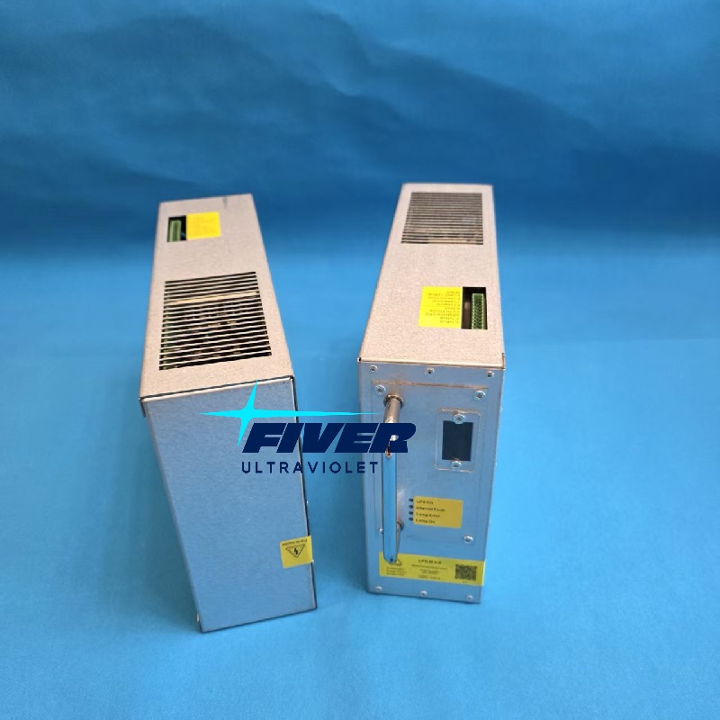
The Alfa Laval LPS M3-6 (Part #9012146-01, Rev 4) is a 6kW electronic ballast controlling 3/6 kW medium-pressure UV lamps in PureBallast BWTS. Common failure indicators include Alarms A122, A131, A160, and front-panel red LED faults. Fiveruvc provides 100% direct OEM-compatible replacement units.

In This Article
1. What Is the LPS M3-6 and Why Does It Matter?
If your vessel runs an Alfa Laval PureBallast ballast water treatment system (BWTS), every time you take on or discharge ballast water, a bank of medium-pressure UV lamps fires up inside the UV reactor to inactivate organisms. Those lamps don't run on the ship's raw 440 VAC power — they need precisely regulated, high-frequency, high-voltage power that ordinary electrical systems can't provide.
That's where the LPS M3-6 comes in. LPS stands for "Lamp Power Supply," and this module (Alfa Laval Part Number 9012146-01, currently at Revision 4) is the electronic ballast that converts three-phase ship power into exactly what a 6 kW medium-pressure UV lamp needs to ignite and sustain its plasma arc.
The system manual puts it plainly: "One LPS feeds power to one UV lamp. The LPS also monitors the function of each UV lamp and takes action if a fault occurs."
In other words, every single UV lamp in your reactor has its own dedicated LPS. If you have 16 lamps, you have 16 LPS modules. And if even one of them fails, that lamp goes dark — which, depending on your water conditions and how many other lamps are already compromised, could push your system below the IMO D-2 compliance threshold and halt your ballast operations.
Understanding how the LPS works, how to diagnose its failures, and when to replace it isn't just a technical exercise — it's operational preparedness that keeps your vessel compliant and on schedule.
Three functions in one module:
Power delivery — 6,000 W high-frequency output per lamp
Lamp monitoring — real-time current, voltage, power, and ignition status via Modbus to the PLC
Fault protection — automatic shutdown on short circuit, over-temperature, or ignition failure
2. How It Works: From Ignition to Dimming
The LPS M3-6 operates in three distinct phases every time a UV lamp starts up. Understanding these phases helps you make sense of what the HMI and LED indicators are telling you during troubleshooting.
Ignition: Lighting the Arc
Medium-pressure UV lamps contain mercury vapor at high pressure. To start the lamp, the LPS generates an ignition pulse exceeding 4,000 Vpp (volts peak-to-peak) at approximately 270 kHz. This high-voltage burst ionizes the mercury vapor, establishing the initial electrical arc inside the quartz tube. The ignition process typically completes within 10 seconds — the system manual specifies that "UV lamps are lit within 10 seconds" during the lamp test procedure.If ignition fails, the LPS reports it to the HMI. Common causes include lamp end-of-life, degraded electrodes, or moisture inside the quartz sleeve causing electrical leakage.
Running: Sustaining the Plasma
Once the arc is established, the LPS switches to running mode, delivering stable high-frequency power at 25 kHz to maintain the plasma arc at the target power level. During normal operation, each LPS outputs approximately 6.0 kW — visible on the HMI as the "Power (kW)" column on Page 4.6.While running, the LPS continuously monitors lamp current, voltage, output power, internal air temperature, heatsink temperature, and fan operation. Any anomaly triggers protective action — from automatic dimming to complete shutdown.
Dimming: Power Optimization
The PureBallast control system uses a closed-loop strategy. The UV sensor (QT201-50) measures actual UV intensity in the reactor. Based on water transmittance (UVT) and flow rate, the PLC calculates the required UV dose and adjusts each LPS's power output accordingly. The system manual explains: "The UV intensity the system is aiming to attain by increasing or decreasing power effect to the LPS controlling the dimming of the UV lamps." Manual dimming is also available for testing — operators can set power output between 50% and 100% of full effect. This dimming range is one reason a replacement LPS must be fully compatible: a unit that can't dim properly will cause the PLC to lose dose control.
Fail-Safe Shutdown
The LPS is integrated into the PureBallast safety system. When a critical alarm is issued — such as "no water in the UV reactor" (detected by level switch LS201-29) — the fail-safe function inactivates all LPS units and immediately cuts power to all UV lamps. This prevents the lamps from operating dry, which would cause catastrophic overheating.
A hardware-level shutdown path exists too: the safety relay KS1 in the LDC cabinet can cut all LPS power regardless of the PLC software state. If someone hits the emergency stop button on the cabinet door, KS1 triggers and all lamps die instantly.
3. Inside the Cabinet: How LPS Units Are Organized
The number of LPS units in a PureBallast system depends on the reactor size — which in turn depends on the vessel's ballast flow rate capacity. Here's how they're distributed:
| Cabinet | LPS Positions | Notes |
|---|---|---|
| Electrical Cabinet (EC) | LPS 1 – 5 | Main cabinet, integrated with the control system |
| Lamp Drive Cabinet 1 (LDC 1) | LPS 6 – 10 | Add-on for medium systems |
| Lamp Drive Cabinet 2 (LDC 2) | LPS 11 – 16 | Second add-on for largest systems |
The system manual notes: "The lamp drive cabinet is an add-on electrical cabinet required for larger system sizes. One or two LDC will be added depending on UVR size. The cabinets are almost identical, but LDC 1 contains 5 LPS and LDC 2 contains 6 LPS."
Each LPS has its own circuit breaker (labeled Q101–Q105 for LPS 1–5, etc.) and is monitored by a microswitch (MS132) that triggers Alarm A122 if a breaker trips. This means you can isolate and identify a faulty LPS by systematically switching off individual breakers — a technique we'll cover in the troubleshooting section.
DIP Switch Addressing
Each LPS module has DIP switches (switches 4–8) that assign a unique binary address, allowing the PLC to communicate with each unit individually. LPS 1 = SW4 on, LPS 2 = SW5 on, LPS 3 = SW4 + SW5, and so on through LPS 16. When replacing an LPS, always verify the DIP switch settings match the unit being replaced — incorrect settings cause Alarm A160 ("No response from LPS").
4. LED Diagnostics: Your First Troubleshooting Tool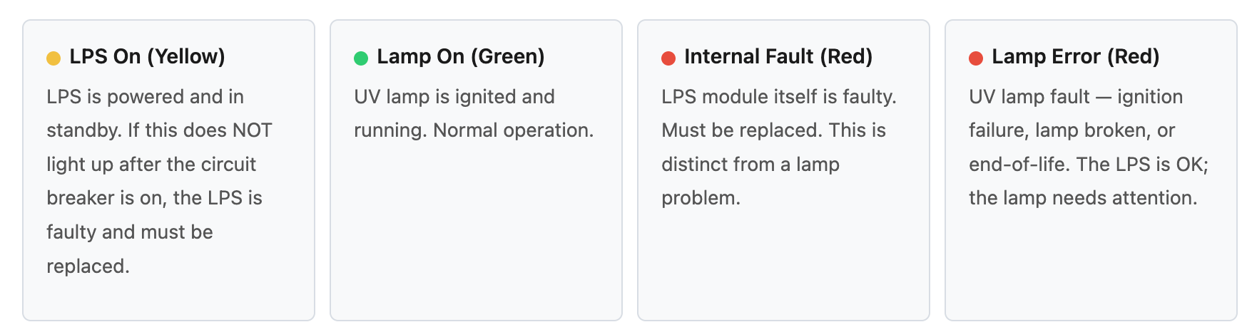
Before you even touch the HMI, the four LEDs on each LPS front panel give you an instant read on what's happening. These are your fastest diagnostic tool — and they're often overlooked by operators who go straight to the screen.
Tips: Quick diagnostic rule from the field guide: During a lamp test, if "LPS On" and "Lamp On" are both lit, everything is working. If "Internal Fault" lights up, the LPS is broken — replace it. If "Lamp Error" lights up, swap the UV lamp with a new one to confirm whether the lamp (not the LPS) is the problem.
5. HMI Page 4.6: Reading the LPS Status Screen
The PureBallast HMI has a dedicated LPS monitoring page (Page 4.6) accessible from the Advanced Operator login level. This page gives you real-time diagnostic data for every LPS in the system — 11 columns of information per LPS:
| Column | What It Tells You |
|---|---|
| Power (kW) | Measured output to the UV lamp. Normal = 6.0 kW. Zero = lamp off or fault. |
| Lamp On | Green = lamp running. Grey = lamp stopped. |
| Ignition | Red = ignition failure. |
| LPS OK | Green = LPS healthy. Red = LPS in fault state. |
| Short Circuit | Red = short circuit alarm (typically water ingress into the lamp). |
| Lamp Open | Red = no lamp connected, circuit open. |
| Air Temp Fault | Red = internal LPS air temperature too high. |
| Heatsink Fault | LPS internal heat protection tripped — electronics overheating. |
| Fan Fault | LPS cooling fan broken — forced air cooling lost. |
If you're investigating an LPS issue, Page 4.6 should be your first stop after checking the front-panel LEDs. The combination of columns tells a complete story — for example, "Short Circuit" red + "LPS OK" red means water has likely entered the quartz sleeve, causing the LPS to detect a short and shut down to protect itself.
6. Alarm Codes You Need to Know
The PureBallast system generates specific alarms when LPS issues arise. Here are the ones that matter most:
| Code | Alarm | What It Means & What to Do |
|---|---|---|
| A122 | LPS fuse alarm (MS132) | Circuit breaker tripped. Check fuses Q101–Q105 and F2. A repeated trip means the LPS has an internal short — replace it. |
| A131 | Too many failed lamps | System has dropped below compliance threshold. Check Page 4.6 to see which lamps are down. Replace faulty lamps and/or LPS units. |
| A160 | No response from LPS | Communication lost. Check cables, connectors, and DIP switch settings. Replace LPS if hardware is faulty. |
| A161 | LPS communication error — reactor shutdown | Severe failure. Reactor is shut down. Same troubleshooting as A160. |
| W165 | LPS in fault state | LPS reported an internal fault. Check the red LED on the front panel. |
| W132 | Estimated UV lamp lifetime exceeded | Recommended to replace UV lamps. Note: this is about lamps, not the LPS — but running end-of-life lamps stresses the LPS. |
7. Field Troubleshooting: Two Common Scenarios
The following procedures are condensed from the Alfa Laval LPS Trouble Shooting Guide. They cover the two most common LPS failure scenarios you'll encounter at sea.
Scenario 1: 440 VAC Low Insulation Alarm
This alarm typically means water has found its way into the lamp power circuit — usually through a compromised quartz sleeve or cable gland.
Power up the system and acknowledge all alarms at the HMI.
Press reset buttons on the LDC cabinet. If the blue reset clears, proceed. If it doesn't, the KS1 safety relay is triggered — contact Alfa Laval service.
Switch on the 440 VAC main switchboard. If a low insulation alarm appears, isolate the fault.
In the LDC cabinet, switch off individual LPS circuit breakers one by one (Q101 → Q105) to identify which LPS circuit is causing the alarm.
Once identified, power off the LDC cabinet and remove the affected LPS outgoing power connector (press the red latch on the black connector and pull down).
Open the UVR reactor and inspect the UV lamp(s) for broken, burnt, or water-damaged lamps. Check for water ingress in the quartz sleeve.
Open the UVR junction box and inspect for water ponding, corrosion at cable glands, or moisture damage.
Perform a megger test at 1,000 VDC on the lamp power cables (phase to ground). Acceptable: > 2.5 GΩ. Below 2.5 GΩ means water has compromised the insulation — the cable must be replaced.
Scenario 2: LPS or UV Lamp Failure Test
When you're not sure whether the problem is the LPS or the lamp, this procedure isolates the issue.
Power the LDC cabinet. Press reset buttons. Acknowledge alarms.
Check that no LPS circuit breaker has tripped. Observe the LPS front panel LEDs.
If "LPS On" yellow LED does NOT light up after the circuit breaker is on, the LPS is short-circuited — replace it.
If all LEDs are normal, line up the system for a lamp test: enable manual mode, open overboard valves, run seawater cooling pump, open all cooling water valves.
Verify level switch LS201-29 indicates wet condition. Record initial temperature from TT201-33.
From the UVR popup, start each LPS one by one. UV lamps should light within 10 seconds.
Monitor temperature — if TT201-33 exceeds 60°C, switch off lamps immediately. Keep below 50°C during testing.
Verify all LPS power outputs show approximately 6.0 kW on the HMI.
Check the LPS front panels: "LPS On" + "Lamp On" = OK. "Internal Fault" = replace LPS. "Lamp Error" = swap UV lamp.
Safety warning: "Manual operation of LPS may only be performed after cable connection. If not, hazardous situations may arise which, if not avoided, will result in death or serious injury." Always ensure all power cables are connected before operating the LPS. Before maintenance of the EC and LDC: switch off all power and follow lockout/tagout procedures.
8. When and How to Replace an LPS
Replace the LPS when:
"Internal Fault" LED is lit red on the front panel
"LPS On" yellow LED does not light up after the circuit breaker is turned on
Alarm A160 persists after checking cables, connectors, and DIP switch settings
Alarm W165 recurs after reset
Air temp fault, heatsink fault, or fan fault appear on Page 4.6 — internal hardware failure
LPS circuit breaker (MS132) repeatedly trips — internal short circuit
Replacement Procedure
The system manual (Section 7.3.4–7.3.5) provides the official procedure:
Switch off power to the affected LPS circuit breaker.
Disconnect the Modbus communication cable and the lamp power output connector (press red latch, pull down).
Remove the old LPS module from the cabinet slot.
Set DIP switches on the new LPS to match the address of the replaced unit.
Insert the new LPS and secure it.
Reconnect power input, lamp output connector, and Modbus cable.
Switch on the circuit breaker and verify the "LPS On" yellow LED lights up.
Perform a lamp test to verify the new LPS ignites the UV lamp and outputs 6.0 kW.
Verify HMI Page 4.6 shows all green status indicators for the replaced LPS.
Spare Parts Recommendation
Given that a single LPS failure can render one UV lamp non-functional — potentially dropping the system below the compliance threshold — we recommend keeping at least one spare LPS M3-6 unit onboard at all times. For vessels operating in low-UVT waters where all lamps must be operational, consider carrying two spares.View our LPS M3-6 replacement page →
Compatible UV Lamps
The LPS M3-6 (9012146-01) is compatible with these Alfa Laval medium-pressure UV lamp part numbers:
| Lamp P/N | Length | System |
|---|---|---|
| 9009521-80 | 535 mm | PureBallast 3.1 / 3.2 Compact |
| 9007810-80 | 545 mm | PureBallast 3.0 / 3.1 Flow |
| 579367-98 | 435mm | Earlier PureBallast 2.0 / 3.0 |
| 582034-80 | 445mm | Earlier PureBallast 2.0 |
9. Why One Dead LPS Can Stop Your Ship
The IMO Ballast Water Management Convention (D-2 standard) and USCG regulations require that ballast water treatment systems achieve a minimum UV dose to inactivate organisms. If even one UV lamp isn't operating at full power because its LPS has failed, the system's total UV output drops — potentially falling below the compliance threshold.
The PureBallast control system continuously monitors LPS output power. If too many lamps fail (Alarm A131), the system declares "process not compliant" and prevents new ballast/de-ballast operations from starting. This means a faulty LPS can halt vessel operations until the unit is replaced.
| Failure Scenario | Operational Impact |
|---|---|
| 1 LPS fails (1 lamp down) | System may continue if UV dose still meets threshold — depends on UVT and flow rate |
| Multiple LPS fail | Alarm A131 — system declares non-compliant, new processes blocked |
| LPS communication failure (A161) | Reactor shutdown — immediate halt to ballast operations |
This is why regular maintenance matters. The PureBallast Annual Inspection and Calibration procedure includes checking LPS LED status, reviewing HMI alarm logs, and verifying 6.0 kW output per LPS. Staying ahead of LPS failures is far cheaper than a port state detention.
Need a Replacement Alfa Laval LPS M3-6 Ballast?
Don't let a failed LPS stop your vessel's ballast operations. Fiveruvc provides 100% OEM-compatible replacement units (9012146-01) with fast global marine delivery. contact us via: jerry@fiveruvc.com
10. FAQ
What does "LPS" stand for in Alfa Laval PureBallast?
LPS stands for "Lamp Power Supply." It is the electronic ballast module that ignites and powers each 6 kW medium-pressure UV lamp in the PureBallast UV reactor. The LPS M3-6 (P/N 9012146-01) is the specific model used in PureBallast 3.x systems.
How many LPS units are in a PureBallast system?
It depends on system size: small systems (e.g., 85 m³/h) have 5 LPS units in the Electrical Cabinet; medium systems have 10 (5 in EC + 5 in LDC 1); the largest systems have 16 (5 in EC + 5 in LDC 1 + 6 in LDC 2). Each LPS powers exactly one UV lamp.
How do I know if the LPS or the UV lamp is faulty?
Check the LED indicators on the LPS front panel: if "Internal Fault" (red) is lit, the LPS itself is faulty. If "Lamp Error" (red) is lit, the LPS is OK but the UV lamp needs replacement. You can also check HMI Page 4.6 for detailed fault status.
Can one LPS power two UV lamps?
No. The system manual explicitly states "one LPS feeds power to one UV lamp." Each UV lamp requires its own dedicated LPS M3-6 unit. A 16-lamp system needs 16 LPS modules.
What is the LPS dimming range?
The LPS can be dimmed from 50% to 100% of full power (3 kW to 6 kW). The PureBallast control system adjusts dimming automatically based
on UV sensor feedback and water transmittance (UVT). Manual dimming is available for testing.
What input voltage does the LPS M3-6 require?
The OEM label specifies 400–440 VAC, 50/60 Hz, 3-phase. The wide operating range (per aftermarket equivalents) is 360–480 VAC,
accommodating shipboard power fluctuations.
Post time:2026-08-12
